New in v8.20
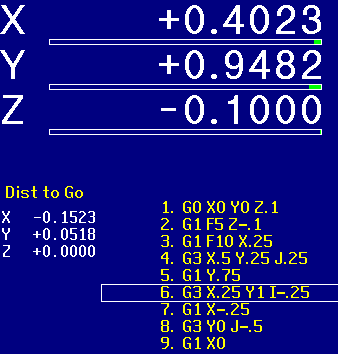
The distance-to-go DRO is not displayed by default.
To turn on the distance-to-go DRO:
New in v8.10
The runtime graphics feature is turned off by default.
To turn on runtime graphics:
Once turned on, the runtime graphics feature stays on until
turned off, or until the control power is switched off.

You can change the default so that runtime graphics are on every day (at power-up) unless you explicitly turn them off.
To make runtime graphics be on by default:
If runtime graphics are on by default, you can still turn them off using the Run menu as described previously.
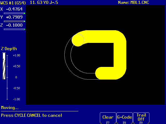
When runtime graphics are on, you can press F8 as the job runs to switch back and forth between the graphics display and the G code display.
New in v8.00
Coordinate rotation applies to the X and Y axes only, to compensate for a fixture that is out of square. It does not apply to the Z axis, and so cannot compensate for a fixture that is not level.
Each coordinate system (fixture) has a separate rotation angle. If you are working with multiple vises, you will want to measure the rotation angle separately for each one.
You can measure coordinate rotation either before or after you set the part zero location on the X and Y axes. If you set the part zero location first, then measure coordinate rotation, the rotation is done around part zero (X0 Y0). That point will remain fixed, while all other points rotate around it.
If you measure coordinate rotation first, then set the part zero location, the control will compensate for rotation as it locates part zero. Thus, if you will be touching off on a position that is not X0 Y0, you should measure coordinate rotation first.
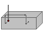
Coordinate system rotation can be measured with a touch probe or manually.
To set coordinate system rotation with a touch probe:
To set coordinate system rotation manually:
 If a coordinate rotation is set for the current coordinate system,
a rotation icon will appear between X and Y on the DRO display.
To clear out the rotation corrections for all coordinate systems:
New in v7.50
CAM digitizing traces a single constant-Z contour around the outside of a raised model. It then produces G codes which will cut the contour, optionally taking multiple cutter passes.
New in v8.20
You can use the AUX1, AUX2, etc. keys to quickly set part zeros, power axes on and off, call up one-shot conversational canned cycles, and perform other tasks.
Machine Parameters 188 and following select AUX key functions. Parameter 188 is for AUX1; Parameter 189 for AUX2; Parameter 190 for AUX3; and so on. Set the parameter value to select the function you want to assign to the corresponding AUX key.
Possible values are as follows:
| No Function | 0 | Set XYZ Zero | 16 | |
| Enter X Axis Position | 1 | One Shot Bolt Hole Circle | 17 | |
| Enter Y Axis Position | 2 | One Shot Drill Array | 18 | |
| Enter Z Axis Position | 3 | Jog X+ | 21 | |
| Set Position, Absolute | 4 | Jog Y+ | 22 | |
| Set Position, Incremental | 5 | Jog Z+ | 23 | |
| One Shot Drill | 6 | Jog 4th + | 24 | |
| One Shot Circular Pocket | 7 | Jog 5th + | 25 | |
| One Shot Rectangular Pocket | 8 | Jog X- | 31 | |
| One Shot Frame | 9 | Jog Y- | 32 | |
| One Shot Face | 10 | Jog Z- | 33 | |
| Free Axes | 14 | Jog 4th - | 34 | |
| Power Axes | 15 | Jog 5th - | 35 |
The "Enter Axis Position" functions must be used with one of the "Set Position" functions. For example, with Parameter 188 set to 1.0 and Parameter 191 set to 4.0, you could press the AUX1 key to enter an X axis position, then press AUX4 to accept and set the position.
New in v8.00
While editing any Intercon operation, you can plug in the current DRO position from the X, Y, or Z axis simply by typing that letter.
For example, to enter a Rapid move to the current tool position:
You can display a live DRO in the lower left corner of the screen for reference purposes. Press F9/Teach to display the live DRO; Press F9/Teach again to hide it. You do not have to have the live DRO on the screen in order to use the quick Teach feature.
There is no longer any way to zero the DRO (temporarily change part zero) within Intercon for the Teach feature. Instead, you must set the part zero where you want it, using the regular Part Setup screen, before entering Intercon.
The method of editing field values in Intercon has changed slightly. If you want to enter a new value, replacing any previous value, you just start typing as before. However, if you want to modify the previous value without replacing it (e.g. to change one digit or to add or remove a minus sign) you now press the Enter key, then move the cursor where you want it using the arrow keys. Previously you just used the right arrow key immediately without pressing Enter first.
New in v8.00
Cleanout is a new canned cycle in Intercon. The Cleanout operation itself contains all the usual pocketing information: depth, number of passes, rough and finish cut amounts, etc.. It does not contain any information about the horizontal (XY) dimensions of the pocket.
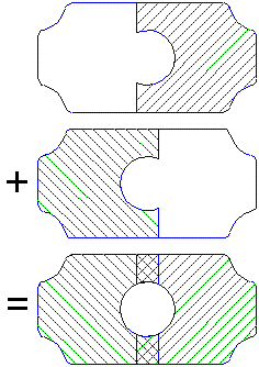 The Cleanout operation is followed by a bracketed series of Line and
Arc moves which define the outline of the pocket. The first
Line simply establishes a starting point. The subsequent Line and
Arc moves become the finished outline. If the outline is not closed (the
last move does not return to the starting point) Intercon will
automatically close it with an assumed straight line.
Cleanout has no provision for island avoidance. If you need to clean
out an irregular-shaped pocket while leaving an island standing inside,
use two or more Cleanout cycles which split the island. Allow at
least a tool diameter of overlap.
New in v8.00
Intercon's Drill, Bore, and Tap cycles now allow rectangular arrays.
You enter the position of the first hole, then the number of holes and hole spacing along the X and Y axes.
A "skip list" allows you to leave selected holes out of the pattern.
New in v8.00
If you have a pattern of single holes (entered with separate XY locations, rather than as Arrays or Bolt Hole Circles), you can now do additional operations on the same set of holes without having to reenter the coordinates.
For example, you would enter individual Drill operations to center drill each of a dozen locations. You could then change tools and use a Drill Repeat to drill through at each location. You could then change tools again and use Tap Repeat to tap all those locations. If you later needed to correct the coordinates of one or more holes, you would only need to change the original center-drilling holes. The through-drill and tap holes would move automatically.
New in v8.00
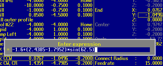
Intercon has supported in-line arithmetic since version 6.00. However, its utility has been limited by the 10-character input box that your formula had to fit in.
In the new software, simply press '=' while entering any number. The extended expression box appears, with room for almost any calculation you may want to make. Enter the expression, then press Enter or '=' again. The calculated result is plugged into your operation and you are ready to proceed.
New in v8.00
New in v8.00
IF/THEN/GOTO new in v8.10
CNC Macro Programming Examples
New in v8.00
MPG jogging at higher speeds will automatically move more smoothly with the new software.
To take advantage of this, you may wish to enable MPG jogging on the 0.010" (x100) increment. To do so, set Parameter 19:
Note: at higher speeds, the control will not respect exact increments as you turn the handwheel. Instead it will switch to a continuous-motion mode where the wheel controls speed. Once you slow back down to a low speed (discrete clicks) then the control will once again move by the exact increments requested.
New in v8.00
To turn on axis load meters, set Parameter 143:
New in v7.08
The Run/Search screen now allows you to start the job at a specific tool number, without having to know the line or block number.
The job will begin at the first tool change where that tool is loaded. If the same tool is called more than once, and you want to start at a later tool change, you must enter the line or block (N) number to search to the later tool change.
New in v7.00
On the graphic preview screen, press F3 to set the graphing range.
This can make it easier to view specific features of a complex part which has many overlapping cuts.
You can enter either line numbers or block (N) numbers at which the graphing should start and end. If you leave the Start point blank, graphing will start at the beginning of the program. If you leave the End point blank, graphing will run to the end of the program.
If you have entered start and end points to limit the graphing range, then want to return to viewing the entire part, press F3 again and delete (blank out) the start and end points.
New in v6.00
You can search to any point in the job and begin running there, with the correct feedrate, Z depth, spindle and coolant, tool length and cutter compensation.
Press F4 for the Run menu, then F2 for Search. Enter the line, block (N), or tool (T) number where you want to start, then press CYCLE START.
If you canceled the previous job before it finished (e.g. with CYCLE CANCEL, Emergency Stop, or TOOL CHECK) then the control will display the line number which was running when you canceled the job. You can accept this number to restart where you left off, or you can enter any other search point you choose.
New in v6.03
While a job is in progress, press TOOL CHECK to interrupt it.
The axes will decelerate to a smooth stop; the Z axis will pull up to the tool change position; and the spindle and coolant will switch off. The control will automatically display the Job Resume screen (F4/Run, F1/Resume).
You can clear chips and measure the part. You can even replace a worn or broken tool, and can go to the Offset Library to measure or enter new tool offsets.
To resume running where you left off, press CYCLE START from the Job Resume screen. You may wish to jog close to the part first, to save time that would otherwise be spent moving to the part at your cutting feedrate.
When you press CYCLE START to resume, the control will restart the spindle and coolant; move X and Y over the beginning of the interrupted cut; move Z down to cut depth; and resume running the program normally.
If you need to back up and restart at an earlier point in the program (for example if the tool broke several moves back) you should press ESC to leave the Resume screen and instead press F2 for the Search screen. The Search line number will default to the line which was running when you pressed TOOL CHECK. You can edit this number to be a few lines back. If you are unsure of the correct starting line, you can preview the search with F8/Graph. When ready, press CYCLE START to start on the chosen line.
New in v7.08
There are now 18 independent part locations, plus 4 reference return points.
New in v7.08
Intercon's Rectangular Pocket, Circular Pocket, and Frame cycles now allow either a ramped plunge at any angle you choose, or a straight-down plunge.
The default is a ramped plunge. The Plunge Angle defaults to 0.0, which means to use a default of 45°. If you choose, you can change the Plunge Angle to suit your cutter: 10° would be a very shallow ramp; 80° would be a very steep one.
If the pocket is not wide enough to allow the cutter to ramp down to your chosen cut depth at your chosen angle, Intercon will zig-zag down in multiple ramps.
If your tool is not suitable for downward cutting at all, choose a straight plunge and insert a drilling operation before the pocket or frame, to drill out the plunge point. For pockets, the plunge will always be in the center of the pocket. For frames, the plunge will be near the back left corner (if climb milling) or the back right corner (if conventional milling). It will be a cutter radius away from the back wall, and will be inside any corner radius. If in doubt about where the plunge point is for a Frame mill, check its endpoint as displayed in the program listing on the left side of the screen.
New in v6.02
Intercon includes a canned cycle for Thread milling.
Entering your program in Intercon, press F5 for Canned Cycles, then F8 for Thread. Fill in the relevant thread dimensions.
The Diameter dimension refers to the final cut taken by the thread mill. For internal threads, this should be the major diameter. For external threads, this should be the minor diameter.
You can request multiple cutting passes, but any after the first are spring passes (retracing the same toolpath as the first pass). If you need to remove more material than your thread mill can cut in one pass, you should enter two or more Thread cycles: the earlier ones cutting to smaller diameters (for internal threads) or larger diameters (for external threads).
The Thread cycle cuts the threads in or on an existing hole or boss. You may need to include Drill, Circular Pocket, and/or Frame cycles before the Thread cycle.
If you choose a single-point cutter, the Thread cycle will spiral down in as many turns as are required to reach the depth you enter.
If you choose a full-form cutter, the Thread cycle will do only one spiral pass, regardless of depth. It assumes the cutter insert has enough teeth to cut the entire thread.
New in v7.06
If you have the rigid tapping option on your machine, Intercon will now allow you to do peck tapping.
On the Tapping canned cycle screen in Intercon, simply enter a depth increment less than the total depth of the hole. Intercon will output multiple G84 tapping cycles, causing the tool to tap down by the requested depth increment; reverse back to the surface; run forward down another increment; and so on to the full depth. Each successive peck will synchronize to the previously cut threads.
Copyright © 2004 Marc Leonard
You are welcome to print out this page for your
own use and for non-commercial distribution, as long as you include
this copyright message.
Last updated 08-Apr-2008 MBL