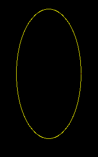
 Freestanding program to machine around an ellipse with given
length, width, and center.
Here are a few examples of what you can do with the advanced macro programming features introduced in version 8.00 and 8.10 of the Centroid control software.
To download these macro files, click on the "download" link with the right mouse button and choose "Save Target As..." or "Save Link As..."; save the ZIP file on your hard drive; then use PKZIP, WinZIP or a similar program to unpack it.
| ELLIPSE | Machine around an ellipse | View | Download |
| BORE | Bore center probing cycle | View | |
| O7383 | Hybrid peck/deep hole drilling cycle | View | |
| POLYGON4 | Clean out polygonal pockets | View |
 Freestanding program to machine around an ellipse with given
length, width, and center.
  ; ELLIPSE.CNC
  ;
  ; Program to mill ellipse
  ;
  ; Modify the following variables as needed:
  ;
  #101 = 0.75   ; length along X axis
  #102 = 0.35   ; length along Y axis
  #103 = 10.0  ; plunge feedrate
  #104 = 20.0  ; cutting feedrate
  #105 = 0.1   ; Z clearance height
  #106 = -0.2  ; Z cut depth
  #107 = 5.0   ; angle increment
  #108 = -1.0  ; the X center position
  #109 = 1.0   ; the Y center position

  G41 D1  ; start up cutter compensation (change D number as needed)

  ;=================================

  O9100
   G1 X[#101 * cos[#110] / 2.0 + #108] Y[#102 * sin[#110] / 2.0 + #109]
   #110 = #110 + #107
  M99

  G0 X[#101/2.0+#108] Y#109 Z#105
  G1 F#103 Z#106
  F#104

  #110 = #107
  M98 P9100 L[360.0/#107]
  G0 Z#105
  G40
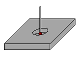
 Subroutine that duplicates the Bore cycle on the Probing menu.
This allows you to build probing operations directly into a part program.
The example shown below works with CNC7 and CNC10 systems.
In CNC11, the sense of the P parameter to M115 and M116 is reversed. This requires that all negative P values change to positive, and vice versa.
In CNC7 and CNC10:
In CNC11:
  ; bore.cnc - Probe the center of a circular bore
  ;
  ;   Marc Leonard
  ;   CNC Services Northwest
  ;   www.cncsnw.com
  ;
  ; Call:
  ;   M98 "bore.cnc"
  ; or:
  ;   G65 "bore.cnc"
  ;
  ; Example:
  ;     M25                  ; move to Z home
  ;     G43 H#9012           ; length compensation for probe
  ;     G0 X0 Y0             ; move over bore (old X0Y0)
  ;     M125/Z-.5 F100 P-15  ; "safe" move down into bore
  ;     M98 "bore.cnc"       ; probe center of bore
  ;     G92 X0 Y0            ; reset X0Y0 to exact center
  ;     M25                  ; back to Z home
  ;

   #1 = #4003     ; save positioning mode (90/91)
   #2 = #4109     ; save feedrate
   #3 = #4001     ; save movement mode (0/1/2/3)

   #24 = #5041    ; save starting X position
   #25 = #5042    ; save starting Y position

   M116/X F#9014 P-#9011     ; fast probe X+
   M115/X#24 F#9014 P#9011   ; move clear
   G1 G91 F#9014 X-#9013
   G90 M116/X F#9015 P-#9011 ; slow probe X+
   #10 = #5041               ; save coordinate of right wall
   M115/X#24 F#9014 P#9011   ; move clear
   M115/X F#9014 P-#9011     ; fast probe X-
   M116/X#24 F#9014 P#9011   ; move clear
   G1 G91 F#9014 X#9013
   G90 M115/X F#9015 P-#9011 ; slow probe X-
   #10 = [#10+#5041]/2.0     ; calculate midpoint between walls
   M116/X#24 F#9014 P#9011   ; move clear
   G1 G91 F#9014 X#9013
   G90 M126/X#10 F#9014 P-#9011  ; move X back to midpoint

   M116/Y F#9014 P-#9011     ; fast probe Y+
   M115/Y#25 F#9014 P#9011   ; move clear
   G1 G91 F#9014 Y-#9013
   G90 M116/Y F#9015 P-#9011 ; slow probe Y+
   #11 = #5042               ; save coordinate of back wall
   M115/Y#25 F#9014 P#9011   ; move clear
   M115/Y F#9014 P-#9011     ; fast probe Y-
   M116/Y#25 F#9014 P#9011   ; move clear
   G1 G91 F#9014 Y#9013
   G90 M115/Y F#9015 P-#9011 ; slow probe Y-
   #11 = [#11+#5042]/2.0     ; calculate midpoint between walls
   M116/Y#25 F#9014 P#9011   ; move clear
   G1 G91 F#9014 Y#9013
   G90 M126/Y#11 F#9014 P-#9011  ; move Y back to midpoint

   G#1 G#3 F#2      ; restore saved modals
  M99
Drilling cycle that will do peck drilling down to 4x the cutter diameter, then revert to the deep-hole (chip clearing) cycle.
  ; Hybrid peck/deep hole drilling macro
  ;  Do G73 to 4x cutter diameter
  ;  then do G83-style, pulling to surface between pecks
  ;  Arguments:
  ;     X, Y  Location of hole
  ;     Z     Final depth
  ;     R     Rapid-to depth
  ;     I     Peck increment for chip breaking
  ;     J     Peck increment for deep-hole
  ;     F     Feedrate
  ;
  ;  Notes:
  ;     Only works in absolute mode (G90), I point return (G98)
  ;     Ends with tool at R plane
  ;     Does not know/use surface height
  ;
  ;  Example:
  ;
  ;    G65 P7383 X1 Y2 Z-4 R.1 I.2 J.15 F6
  ;
  O7383
   G90 G98
   #101 = #5043
   G0 X#X Y#Y Z#R
   #102 = #R - [4.0 * #11000]
   IF [#102 LT #Z] THEN #102 = #Z
   G73 X#X Y#Y Z#102 R#R Q#I F#F
   N20 IF [#102 LE #Z] THEN GOTO 30
    #103 = #102+#9083
    #102 = #102 - #J
    IF [#102 LT #Z] THEN #102 = #Z
    G81 X#X Y#Y Z#102 R[#103]
    GOTO 20
   N30
   G80
  ; G0 Z#101  ; uncomment for return to initial Z level
  M99
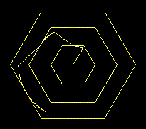
 Clean out triangular, hexagonal, or other regular polygon pockets.
  ; POLYGON4.CNC
  ;
  ; Macro to pocket out interior of a regular polygon
  ;
  ;   Marc Leonard, CNC Services Northwest, 12/21/2004
  ;
  ; Call: G65 "POLYGON4.CNC" X_ Y_ Z_ W_ A_ H_ U_ C_ D_ F_
  ;
  ; Arguments:
  ;
  ;   X, Y  Center point
  ;   Z     Cut depth
  ;   W     Clearance plane (Z)
  ;   A     Number of sides (3 or more)
  ;   H     Height (across flats if A is even; point-to-flat if A is odd)
  ;   U     Stepover
  ;   C     Direction (1 for CCW, 0 for CW)
  ;   D     Angle from center to middle of first flat
  ;   F     Cutting feedrate

   IF #A < 3 || #A > 1000 THEN ERROR

   #108 = 1.0
   IF #C == 0 THEN #108 = -1.0  ; direction of angle progression
   #109 = 360.0 / #A            ; exterior angle
   #110 = 180.0 - #109          ; interior angle

   #120 = #U * 2.0
   IF [#A % 2] != 0 THEN #120 = #U * [1.0 + 1.0/SIN[#110/2.0]]

   ; Loop to calculate factor for length of a side:
   #101 = 0.0      ; angle accumulator
   #102 = 0.0      ; sum of sines
   #100 = #A / 2   ; loop counter
   N1
    #101 = #101 + #109
    #102 = #102 + SIN[#101]
    #100 = #100 - 1
   IF #100 > 0.75 THEN GOTO 1

   #121 = 0.0
   #122 = #D

   ;---- Rapid over center, then feed to depth ----
   G0 X#X Y#Y Z#W
   G1 F[#F * 0.5] Z#Z
   ;----

   N2
    #121 = #121 + #120
    IF #121 > #H THEN #121 = #H

    #112 = #121 / #102     ; length of a side

    #111 = [#112 / 2.0] * TAN[#110 / 2.0] ; distance from center to flat

    #113 = #122 - #108 * #109 / 2.0  ; current direction of travel
    #114 = #X + #111 * COS[#113]   ; last X position
    #115 = #Y + #111 * SIN[#113]   ; last Y position

    ;---- Move out to start of arc ----
    G1 X#114 Y#115 F[#F * 0.5]
    ;----

    #114 = #X + #111 * COS[#122]
    #115 = #Y + #111 * SIN[#122]

    ;---- Arc to middle of flat side ----
    G[2+#C] X#114 Y#115 R#111 F#F
    ;----

    #113 = #122 + #108 * 90.0
    #114 = #114 + #112 * COS[#113] / 2.0
    #115 = #115 + #112 * SIN[#113] / 2.0

    ;---- Move remaining half way along side to first vertex ----
    G1 X#114 Y#115 F#F
    ;----

    #100 = #A - 1   ; loop counter: loop around n-1 full sides

    N3
     #113 = #113 + #108 * #109
     #114 = #114 + #112 * COS[#113]
     #115 = #115 + #112 * SIN[#113]

     ;---- Move to next vertex ----
     G1 X#114 Y#115 F#F
     ;----

     #100 = #100 - 1
    IF #100 > 0 THEN GOTO 3

    #113 = #113 + #108 * #109

    #114 = #114 + #112 * COS[#113] / 2.0
    #115 = #115 + #112 * SIN[#113] / 2.0

    ;---- Move half way along last (first) side ----
    G1 X#114 Y#115 F#F
    ;----

    #113 = #122 + #108 * #109 / 2.0  ; current direction of travel
    #114 = #X + #111 * COS[#113]   ; last X position
    #115 = #Y + #111 * SIN[#113]   ; last Y position

    IF #121 < #H THEN GOTO 4
     ;---- Arc away from wall, only on final pass ----
     G[2+#C] X#114 Y#115 R#111
     ;----
    N4

    #122 = #122 + #108 * #109

   IF #121 < #H THEN GOTO 2

   ;---- Rapid back up to clearance ----
   G0 Z#W
   ;----

  M99
Copyright © 2017 Marc Leonard
Last updated 15-Feb-2017 MBL