Centroid CNC control sales, service, training and support
On CNC11 systems, running in velocity mode or in position ("precision") mode, the Centroid control software often has no information about the amount of current and torque the servo drives are using to achieve the requested moves.1
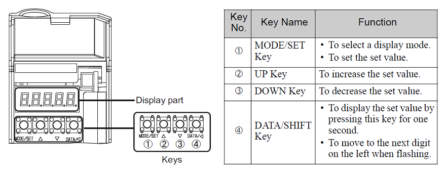
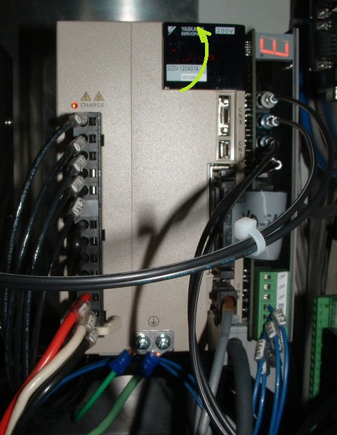
If you would like to see how much torque a drive is actually using (e.g. to verify servo sizing, or to check the effectiveness of the counterbalance on a vertical axis) you can monitor torque using the digital keypad on the Yaskawa drive.
The Sigma V drives provide monitoring displays of many internal values. Monitoring displays are numbered "Unxxx". Instantaneous current/torque output, as a percentage of continuous rated output, is Un002.


If Un002 changes too rapidly to get a useful reading, you can use Un009 instead. Un009 is the accumulated load over a 10-second period, again in percent of continuous rated torque.
1. Beginning with CNC11 v3.14, CNC11 and CNC12 can display axis load meters, provided the analog load signals from the servo drives are wired to analog inputs on an Oak control unit, OpticDirect interface, or PLC analog expansion board; the load values are computed and reported by the PLC program; and meters are configured through Machine Parameter 57.
Beginning with CNC11 v3.16, CNC11 and CNC12 can also run the Drag Diagnostic based on the same PLC-reported load data.
Copyright © 2022 Marc Leonard
Last updated 28-Mar-2022 MBL