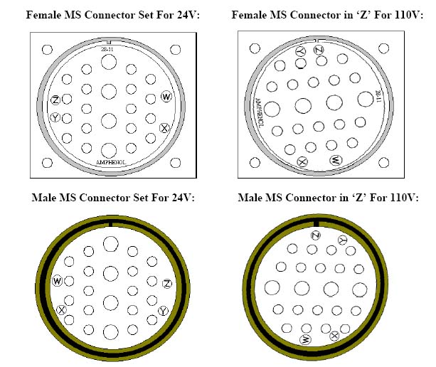
These diagrams show the face (front) of the connectors. When changing the orientation of the female connector, you will be working from the back.
From approximately 1996 through 2001, Centroid's standard rotary axis prewire assumed a 24VDC clamp (holding brake) solenoid in the rotary table. Controls were supplied with a 24VDC power supply, and its power was wired through PLC Output 11 to pins A and B of the 28-11 MS connector.
Beginning in 2001 or so, Centroid began offering a new line of rotary tables which used 120VAC clamp solenoids. Standard cabinet wiring was changed to supply 120VAC through OUT11 to pins A and B.
Initially, no change was made to the connector orientation. This led to problems, as a rotary table with a 24VDC clamp coil could be plugged into a control which supplied 120VAC, burning out the coil.
Beginning in April 2002 Centroid began rotating the 28-11 MS connectors to put the polarizing key in different positions depending on whether the cabinet was wired to supply 24VDC or 120VAC to the clamp solenoid.
The original orientation, with the key adjacent to pin J (at the top of the central column of larger pins) was retained for 24VDC clamps.
A new orientation, with the key adjacent to pin B and the circled "Z" marker, was adopted for 120VAC clamps.
Since then all standard 4-axis controls and Centroid and Golden Sun rotary tables have shipped with 120V clamp wiring, and connectors in the "Z" position.
This document explains how to modify an older control, wired and oriented for a 24VDC clamp, to operate with a new rotary table using a 120VAC clamp.
These changes should be made by a qualified electrical technician. Use the information which follows at your own risk.
The following diagrams show the female (cabinet) and male (rotary
table cable) connectors in their two orientations.

These diagrams show the face (front) of the connectors.
When changing the orientation of the female connector,
you will be working from the back.
Procedure:
The Black and Brown wires on pins A and B supply power to the clamp solenoid coil.
In original 24VDC wiring, +24VDC is wired from the DC power supply, through an in-line fuse, to the common terminal for PLC OUT11 (on an RTK2 PLC unit this is the third terminal from the bottom of plug H11, on the topmost board). OUT11 is wired to pin A of the MS connector (Black wire). 0VDC is wired from the DC power supply directly to pin B of the MS connector (Brown wire).
For 120VAC operation, you will need to make the following changes:
Set the rotary table up, connect its cable to the MS connector, and hook up air to its clamping air inlet.
Power up the controller. If needed, enter the Machine Configuration and Machine Parameter settings for the rotary table. The rotary table manual should include recommended Machine Configuration settings for your table. Additional information may be found here.
To test clamp operation:
Copyright © 2007 Marc Leonard
Top illustration copyright © 2002 Centroid Corporation
Last updated 30-Nov-2007 MBL