| Pin | Signal | Typical Color | Encoder DE9 Pin |
|---|---|---|---|
| A | Enc. ch B | BLU | 8 |
| B | Enc. ch /B | BLU/BLK | 5 |
| C | Enc. ch A | WHT | 7 |
| D | Enc. ch /A | WHT/BLK | 4 |
| E | Enc. ch Z | GRN | 6 |
| F | Enc. ch /Z | GRN/BLK | 3 |
| G | Power Shield | (bare) | n/a |
| H | Enc. Vcc | RED | 9 |
| I | Enc. COM | RED/BLK | 2 |
| K | Enc. shield | (bare) | shell |
| M | Brake Plus * | RED | n/a |
| N | Power Plus | RED | n/a |
| O | Brake Minus * | BLK | n/a |
| P | Power Minus | BLK | n/a |
* Brake connections require an additional cable, and are only required for servo motors with an integral holding brake.
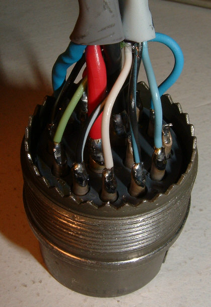
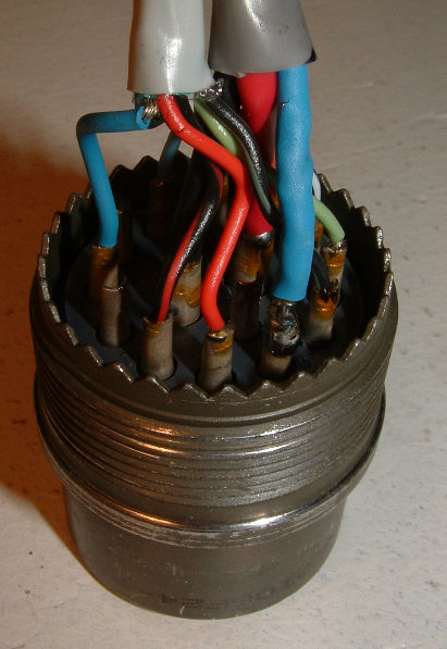
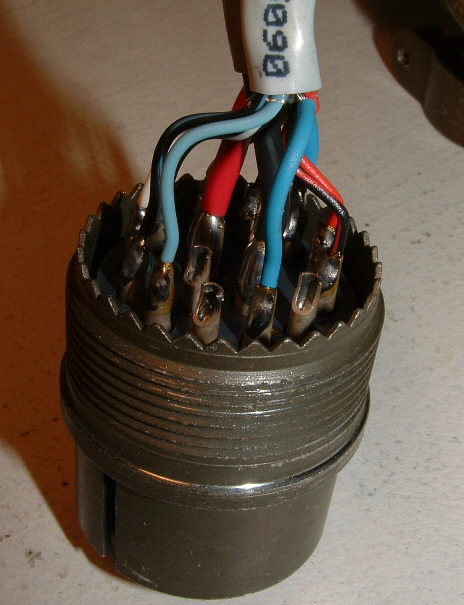
Bare wires (power and encoder shields) should be covered with heat shrink.

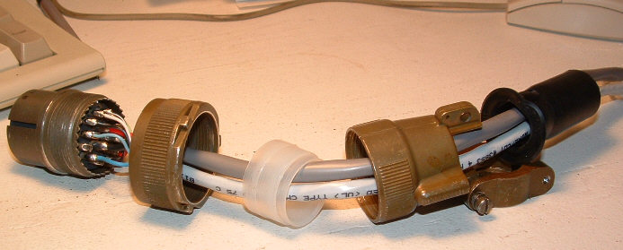
Make sure you slide the threaded collar, plastic sleeve, back shell, and rubber strain relief onto both cables before you start soldering!

View of connector facing pins C and D.

View of connector facing pins H and I. Note power cable shield wire
(in blue heat shrink) going to pin G.
 View of connector facing pins K and L. Note encoder shield wire
(also in blue heat shrink) going to pin K.
The wire colors shown here are typical of Centroid factory production. Your wire colors may vary (especially for Revolution machines).