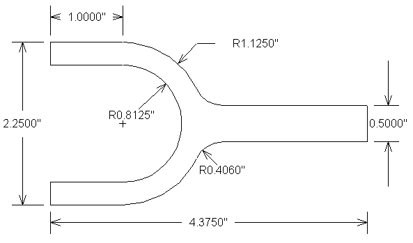
We will cut the part shown below, using cutter radius compensation to adjust for the size of the end mill, and using Intercon's Math Help and Connect Radius features to help with the more difficult aspects of the geometry. We will use Tool #2, a 1/2" end mill.
Note: Intercon may also be named "GGE" , "SFP", or "Centroid Shop Floor Programming" depending on your software version.
♦ Call up Intercon from the CAM menu.
♦ Press F1 to create a new part program.
♦ Enter a name for the part program (e.g. FORK), and your initials.
We are now ready to enter the operations that make up the part program. As always, the first operation is to load the tool we will be using.
♦ Press F4 to select a tool. Enter the tool number and information, and press F10 to accept the tool change operation.
We will climb mill around the profile. When climb milling, we must offset the cutter to the left side of its path around the part.
♦ Press F7 for Comp. Press Space to select Cutter Comp Left. Press F10 to accept.
We are now ready to do a rapid move to get the cutter near the beginning of the cut. We will start at the upper left corner, but will add a short distance for lead-in and lead-out to ensure a clean corner.
♦ Press F1 to insert a Rapid move. Enter the coordinates as X-.1, Y0, Z.1. Press F10 to accept.
♦ Press F2 to insert a Linear move. Change the ending Z coordinate to Z-.25, enter a feedrate of 5 in/min (suitable for a plunge), and press F10 to accept.
♦ Press F2 to insert another Linear move. Change the ending X coordinate to X1.0, increase the feedrate to 10 in/min, and press F10 to accept.
Now we are ready to swing around the first arc. Unfortunately, we do not know the X or Y coordinate of the tangent point where this arc ends (where it blends into the 0.406 fillet radius). Fortunately, Intercon can calculate the fillet radius for us automatically, if we just enter the arc as if it continued all the way down to the horizontal line. Unfortunately, we don't know the X or Y coordinates where the arc would meet the horizontal line either. Fortunately, Intercon's Math Help feature can solve that problem for us.
♦ Press F3 to insert an Arc move. Choose an Arc Type of EP&R (End Point and Radius).
♦ Press F6 for Math Help.
♦ Press F4 to choose the Intersection of Line and Arc scenario.
♦ For the arc center point, enter X1 Y-1.125. For the arc radius enter 1.125. For the line start point enter X0 Y-.875. For the line end point enter X4 Y-.875. Ignore the line angle.
♦ Press F10 to solve the intersection points.
You should see a graphic depiction of the line and the circle, with the two intersection points labeled I1 and I2. Note that the intersection point we want to use is I1 (the one on the right side of the circle).
♦ Press Esc to see the numeric solution (with the X and Y coordinates of the two intersection points).
♦ Press F1 to move the left-hand highlight down to the X coordinate of Intersection Point I1. If necessary, use the up and down arrow keys to move the right-hand highlight to the End X coordinate of the arc.
+----------------Last Solution------------------------Edit Operation----------+
¦  Circle:                                  ¦#0070 Arc mill                   ¦
¦                 CP X:     1.0000          ¦                                 ¦
¦                    Y:    -1.1250          ¦Arc Type          : EP&R         ¦
¦               Radius:     1.1250          ¦Mid:             X: _________    ¦
¦  Line:                                    ¦                 Y: _________    ¦
¦                 SP X:     0.0000          ¦                 Z: _________    ¦
¦                    Y:    -0.8750          ¦End:             X:    1.0000    ¦
¦                 EP X:     4.0000          ¦                 Y:    0.0000    ¦
¦                    Y:    -0.8750          ¦                 Z:   -0.2500    ¦
¦                Angle:     0.0000          ¦Center:          X: _________    ¦
¦  Intersection Point I1:                   ¦                 Y: _________    ¦
¦                    X:     2.0969          ¦                 Z: _________    ¦
¦                    Y:    -0.8750          ¦Angle             : ______  °    ¦
¦  Intersection Point I2:                   ¦Radius            :   0.0000     ¦
¦                    X:    -0.0969          ¦Plane             : XY           ¦
¦                    Y:    -0.8750          ¦Direction         : CW           ¦
¦                                           ¦Connect Radius    :   0.0000     ¦
¦                                           ¦Feedrate          :   1.0000     ¦
¦                                           ¦Angle <= 180°     : Yes          ¦
¦                                           ¦                                 ¦
+-----------------------------------------------------------------------------¦
¦   ↓   ¦  ↑   ¦Copy →¦     ¦      ¦      ¦      ¦Gr Sol¦      ¦      ¦Cancel ¦
¦  F1   ¦  F2  ¦  F3  ¦     ¦      ¦      ¦      ¦  F8  ¦      ¦      ¦  ESC  ¦
+-----------------------------------------------------------------------------+
♦ Press F3 to copy the X coordinate from the Math Help solution to the Arc operation. Note that both highlights automatically advance to the next line (the Y coordinates). Press F3 to copy the Y coordinate as well.
♦ Press Esc to dismiss the Math Help solution screen.
♦ Enter the arc radius (1.125) and verify that the direction is correct (CW). Press F10 to accept.
♦ Press F2 to insert a Linear move. Change the X endpoint to X4.375 and press F10 to accept.
♦ Press F2 to insert another Linear move. Change the Y endpoint to Y-1.375 and press F10 to accept.
♦ Press F2 to insert another Linear move.
This move must also go to where it meets the 1.125 radius circle. We could use Math Help again to find the coordinates, but it is simpler to recognize that this is a symmetric part, and that the X coordinate is the same as the one we found before. It is displayed on the left side of the screen as the X endpoint of operation number 0070.
+-------------Current Part:  FORK----------------------Edit Operation----------+
¦  Operation             End Position        ¦#0100 Linear mill                ¦
¦  #    Type        X         Y         Z    ¦                                 ¦
¦0010 Header      0.0000    0.0000      Home ¦End:             X: ___4.3750    ¦
¦0020 Tool#2      0.0000    0.0000      Home ¦                 Y:   -1.3750    ¦
¦0030 Comp Lft    0.0000    0.0000      Home ¦                 Z:   -0.2500    ¦
¦0040 Rapid      -0.1000    0.0000    0.1000 ¦Angle             :    0.00°     ¦
¦0050 Line       -0.1000    0.0000   -0.2500 ¦Length            :    0.0000    ¦
¦0060 Line        1.0000    0.0000   -0.2500 ¦Connect Radius    :    0.0000    ¦
¦0070 Arc CW      2.0969   -0.8750   -0.2500 ¦Feedrate          :   10.0000    ¦
¦0080 Line        4.3750   -0.8750   -0.2500 ¦                                 ¦
¦0090 Line        4.3750   -1.3750   -0.2500 ¦                                 ¦
¦0100                                        ¦                                 ¦
¦0110 End Prog    4.3750   -1.3750      Home ¦                                 ¦
¦                                            ¦                                 ¦
¦                                            ¦                                 ¦
¦                                            ¦                                 ¦
¦                                            ¦                                 ¦
¦                                            ¦                                 ¦
¦                                            ¦                                 ¦
¦                                            ¦                                 ¦
+------------------------------------------------------------------------------¦
¦Abs/Inc¦      ¦      ¦      ¦      ¦ Math ¦Solutn¦Graph ¦Teach ¦Accept¦Cancel ¦
¦  F1   ¦      ¦      ¦      ¦      ¦  F6  ¦  F7  ¦  F8  ¦  F9  ¦ F10  ¦  ESC  ¦
+------------------------------------------------------------------------------+
♦ Enter this value (2.0969) for the X endpoint and press F10 to accept.
♦ Press F3 to insert an Arc move. Enter the endpoint as X1 Y-2.25, and the radius as 1.125. Change the direction to CW if necessary. Press F10 to accept.
♦ Press F2 to insert a Linear move. Change the X endpoint to X0 and press F10 to accept.
♦ Press F2 to insert another Linear move. Change the Y endpoint to Y-1.9375 (the 2.25 width, divided in half, plus the .8125 radius). Press F10 to accept.
♦ Press F2 to insert another Linear move. Change the X endpoint to X1 and press F10 to accept.
♦ Press F3 to insert an Arc move. Change the arc type to CP&A (Center Point and Angle). For the center point enter X1 Y-1.125. For the angle enter 180 degrees. Change the direction to CCW if necessary. Press F10 to accept.
♦ Press F2 to insert a Linear move. Change the X endpoint to X0 and press F10 to accept.
♦ Press F2 to insert another Linear move. Change the Y endpoint to Y.1 and press F10 to accept.
♦ Press F1 to insert a Rapid move. Change the Z endpoint to Z.1 and press F10 to accept.
We are done with the complete contour, and must now turn cutter radius compensation off before we go anywhere else (e.g. to a repeat of this feature, to another feature, or to a tool change).
♦ Press F7 for Comp. Press Space as needed to select Cutter Comp Off, then press F10 to accept.
We are done adding operations, so we can leave Insert mode.
♦ press Esc to leave Insert mode and go to Edit mode. The current mode is displayed above the right side of the screen.
The completed part program should look something like this:
+-------------Current Part:  FORK-------------------------Edit Part------------+
¦  Operation             End Position        ¦                                 ¦
¦  #    Type        X         Y         Z    ¦                                 ¦
¦0030 Comp Lft    0.0000    0.0000      Home ¦                                 ¦
¦0040 Rapid      -0.1000    0.0000    0.1000 ¦                                 ¦
¦0050 Line       -0.1000    0.0000   -0.2500 ¦                                 ¦
¦0060 Line        1.0000    0.0000   -0.2500 ¦                                 ¦
¦0070 Arc CW      2.0969   -0.8750   -0.2500 ¦                                 ¦
¦0080 Line        4.3750   -0.8750   -0.2500 ¦                                 ¦
¦0090 Line        4.3750   -1.3750   -0.2500 ¦                                 ¦
¦0100 Line        2.0969   -1.3750   -0.2500 ¦                                 ¦
¦0110 Arc CW      1.0000   -2.2500   -0.2500 ¦                                 ¦
¦0120 Line        0.0000   -2.2500   -0.2500 ¦                                 ¦
¦0130 Line        0.0000   -1.9375   -0.2500 ¦                                 ¦
¦0140 Line        1.0000   -1.9375   -0.2500 +-------------Status--------------¦
¦0150 Arc CCW     1.0000   -0.3125   -0.2500 ¦ Tool #:2   Diameter:   0.5000   ¦
¦0160 Line        0.0000   -0.3125   -0.2500 ¦              Length:   1.0000   ¦
¦0170 Line        0.0000    0.1000   -0.2500 ¦ Cutter Compensation:None        ¦
¦0180 Rapid       0.0000    0.1000    0.1000 ¦ Feedrate:    10.0000            ¦
¦0190 Comp Off    0.0000    0.1000    0.1000 ¦ Coolant:  Off                   ¦
¦0200 End Prog    0.0000    0.1000      Home ¦ Spindle Speed:Off               ¦
+------------------------------------------------------------------------------¦
¦Modify ¦Insert¦Delete¦Undel ¦ Copy ¦ Move ¦      ¦Graph ¦      ¦      ¦Cancel ¦
¦  F1   ¦  F2  ¦  F3  ¦  F4  ¦  F5  ¦  F6  ¦      ¦  F8  ¦      ¦      ¦  ESC  ¦
+------------------------------------------------------------------------------+
♦ Press F8 for a graphic view of the part program.
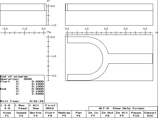
Note that we still have sharp corners where the 0.406 fillets should be.
♦ Press Esc to leave the graphics screen. Press the up arrow key to move the highlight back up to the first arc (operation 0070). Press F1 to modify that operation.
♦ Use the down arrow key to highlight the Connect Radius field. Enter 0.406 and press F10 to accept the change.
♦ Go down to the line (operation 0100) which leads to the second arc, and modify it to also have a 0.406 connect radius. Press F10 to accept.
You always enter the connect radius in the first of the two operations you want to blend.
♦ Press F8 for the graphic view.
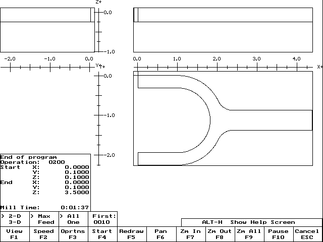
Intercon has automatically inserted the connecting radii between the lines and arcs, saving us the trouble of finding endpoints or centers for the fillets.
♦ Press Esc to leave the graphics screen.
We are done with the whole program.
♦ Press Esc to leave Edit mode and return to the Intercon main screen.
♦ Press F5 for Post. This will save the Intercon part program (FORK.ICN), write the G codes (FORK.CNC), and take us back to the main control screen.
♦ Press F8 for the G code graphic screen.
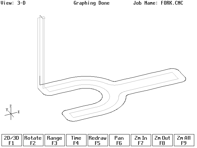
Note that this screen, unlike the one in Intercon, shows the effect of cutter radius compensation. The gray lines are the part outline as we programmed it. The yellow lines are the cutter center path, offset from the part by the radius of the cutter.
Back to on-line tutorials page
Copyright © 2000 Marc Leonard
You are welcome to print out this tutorial for your
own use and for non-commercial distribution, as long as you include
this copyright message.
Last updated 08-Jul-2000 MBL
![]()