Centroid CNC control sales, service, training and support
Hydraulic pressure to operate those devices is usually controlled by solenoid valves, which are in turn operated by the CNC control's PLC.
In order to design the PLC logic for a given device, it is important to understand how the solenoid valves for that device work.
Most modern solenoid valves are provided with a standard porting diagram, which shows how the valve operates in its different positions, and how it shifts from position to position.
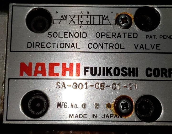
Here is a typical solenoid valve, with its porting diagram on the valve body.

On a printed hydraulic schematic, that diagram would look like this:
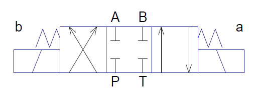
This particular valve has three positions:
The diagram can be broken down into component parts.
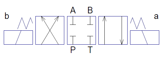
The three porting diagrams in the middle show what happens in each of the three positions.
By convention, the port labels — A, B, P and T — are only printed on the center position diagram, but they are implicitly present on the other position diagrams as well.
The 'a' and 'b' actuator diagrams on each side show how the valve is shifted from one position to another.
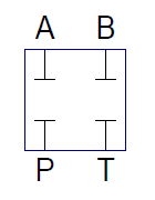 |
In the center position, all ports are blocked. Whatever oil is in the A and B lines is trapped, but no further pressure is applied. |
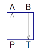 |
When shifted to the 'a' side, port A receives pressure, and port B drains back to the tank. |
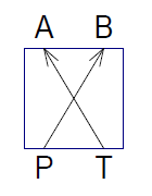 |
When shifted to the 'b' side, port B receives pressure, and port A drains back to the tank. |
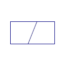 |
The coil symbols on each side show that when power is applied to that solenoid coil, the valve shifts to that position. |
 |
The spring symbols on each side show that when power to that solenoid coil is turned off, the valve springs back to its center position (all ports blocked, in this example). |
Given its porting and spring-to-center action, this valve is useful for jogging operation: as long as it is powered to one side or the other, the piston of the cylinder that is attached to the A and B ports will move in or out. As soon as coil power is turned off, oil flow is blocked, and the piston stops. When stopped, the piston will resist being pushed to one side or the other, but will not apply any continuous force.
If continuous force is required with this type of valve, then power must be continuously applied to one coil or the other.
Copyright © 2023 Marc Leonard
Last updated 11-Jan-2023 MBL