Centroid CNC control sales, service, training and support
This is a simple device for verifying encoder signals, to test suspect encoders and encoder cables.
The device shown is for Centroid-standard DC servo encoders and spindle encoders, with just A, B and Z channels. AC-servo encoders with commutation channels require a 15-pin connector and additional LEDs.
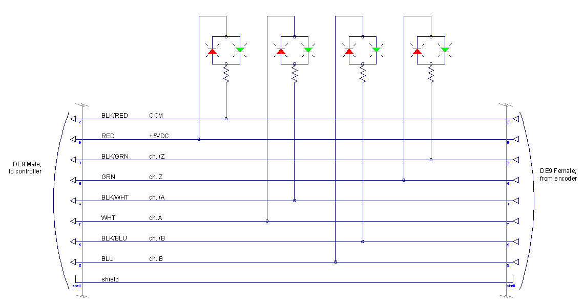
The device consists of a DE9 (often called DB9) feed-through module and terminal block, which allows us to install bi-color LEDs across the power supply and across each of the encoder's differential channels. The LEDs light up green when powered in one direction, and red when powered in the other direction.
The LEDs are connected as follows, and have the following meanings:
| Terminals | Indications |
|---|---|
| 6-3 | Green = Z channel high Red = Z channel low Off = Z channel not driven |
| 7-4 | Green = A channel high Red = A channel low Off = A channel not driven |
| 8-5 | Green = B channel high Red = B channel low Off = B channel not driven |
| 9-2 | Green = 5VDC power good Red = 5VDC polarity backward Off = No 5VDC power |
The cathodes of the LEDs (indicated by a flat cutout in the plastic lens and a shorter lead) should be on the upper terminals (6, 7, 8 and 9).

The device can be used to test encoders in place in the control, by connecting it in-line between the encoder and the Centroid control board. For that you will typically need a male-female DE9 extension cable.
It can also be used to test encoders offline (separate from the control), using its own 5VDC supply. Never plug in the 5VDC supply when the test fixture is connected to a Centroid control board.
With 5VDC power supplied, but with no encoder connected (or with an encoder connected that has dead line driver outputs), only the right-most LED will light.
Here we are testing an encoder offline, without a Centroid control board. The encoder is connected to the test fixture via a DE9 extension cable. 5VDC power is coming from the wall adapter.
At this moment, power is applied (green); the encoder's A channel is active (green); and the encoder's B and Z channels are inactive (red).
If we were to turn the motor or encoder slowly forward (CW, as viewed from behind) the A and B channels would change rapidly, with B leading A:
Here we are doing a similar test, but with the test fixture plugged into the Centroid control board via another DE9 extension cable. The wall adapter is unplugged, as 5VDC is now supplied by the control. The encoder will count normally on the control software screen, in addition to being visible on the test fixture.
The test fixture can also be used as a test point for a volt meter. If all is working properly, then we should see approximately 5VDC between pins 9 and 2, and we should see approximately plus or minus 3VDC across each differential channel pair (6 to 3, 7 to 4, and 8 to 5).
| LED indication | Possible cause |
|---|---|
| Power good, A B and Z all off | Encoder disconnected Faulty encoder (dead line driver) |
| A and B lit, but do not change as encoder turns | Broken or loose code disc in encoder |
| A and B sometimes lit, sometimes off as encoder turns | A and B channel wiring mixed |
| Z changes red/green rapidly as encoder turns | Z channel wiring crossed with A or B channel |
| Z channel green except for brief red flash | Z channel polarity backward (pins 3 & 6 swapped) |
| A leads B in forward rotation | A and B channels swapped, or A or B polarity backward * |
Copyright © 2017 Marc Leonard
Last updated 27-Dec-2017 MBL